
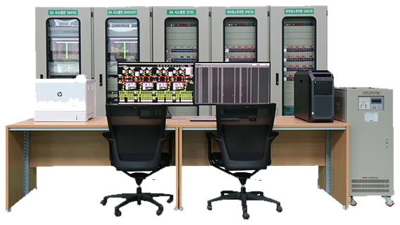
Digital Substation Automation Operation System
The Digital Substation Automation Operation System is an HMI (Human Machine Interface) system that presents operating information on each facility in an IEC 61850-based SA (Substation Automation) digital substation to the operator.
Main components
- SA operating device that communicates with the IEDs in the substation via IEC 61850, presents operating and status information of each facility to the operator, and forwards operator control commands to the IEDs
- Gateway with IEC 61850 and DNP (Distributed Network Protocol) communication that connects the IEDs and RTUs in the substation via those two protocols and links the operating and status information of each facility to the SCADA system
- SA monitoring and diagnosis device that stores and analyzes all traffic on the IEC 61850 network in real time, provides communication data from before and after faults or abnormal conditions of power facilities, and monitors and diagnoses the substation communication system
System configuration and explanation
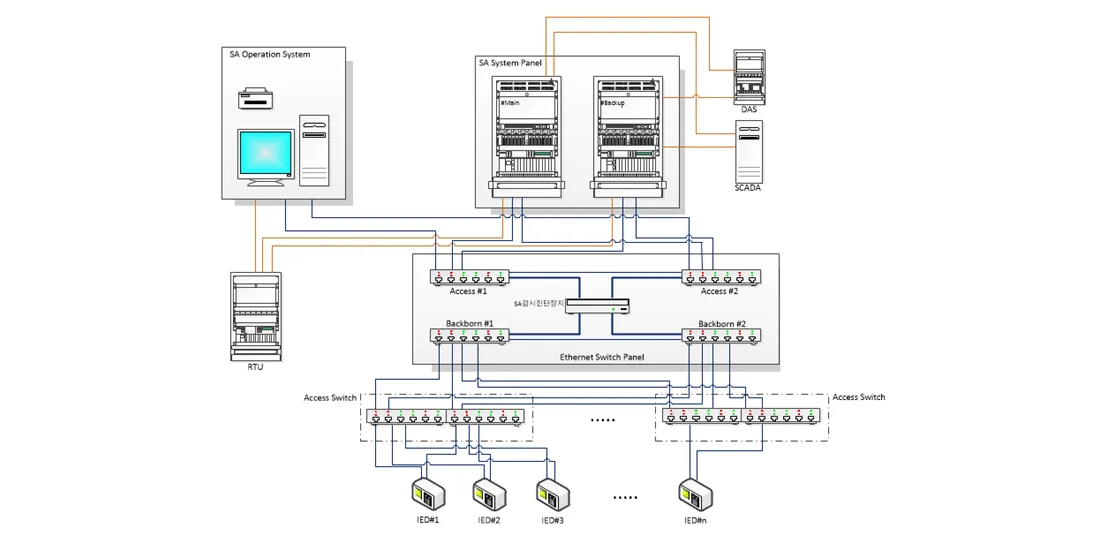
1. SA operation device
Provides the operator interface for the SA system. It acquires operating data from field devices such as IEDs and RTUs, maintains the database, and presents acquired data and event history on screen for operators.
2. Gateway (information connecting device)
Acquires and processes operating information of the electric power facilities in the substation, forwards data received from IEDs and RTUs to the substation operating system and DAS, and passes control commands back to the IEDs and RTUs to execute them.
3. Operating data printer
Prints operating data such as events and reports.
4. Standard time synchronizing device
A server that receives standard time from GPS and synchronizes all SA system devices in the substation.
5. Ethernet switch
Connects the IEDs, SA operating devices, monitoring/diagnosis devices and gateways in the substation. It consists of access switches connected to each device and a backbone switch connecting the access switches.
6. SA monitoring and diagnosis device
Monitors and diagnoses operating information according to the IEC 61850 communication rules. All data exchanged between the SA operating device and the IEDs is stored and accessible through a web interface. Network status and Report/GOOSE monitoring are displayed on screen, and stored data can be filtered and re-saved by time or device.
7. Panel configuring information
Comprises the SA system section (main/backup, E/S) including the gateway, and the SA Ethernet switch section.
Key Functions and Features
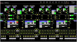
1. HMI Viewer - Real-time facility and measurement monitoring - Issues device control commands
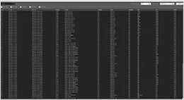
2. HMI Data Viewer - Real-time display of IED/RTU events - Displays monitoring/measuring point information from the DB
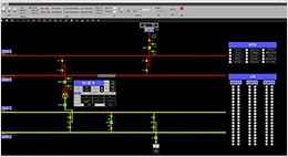
3. HMI Graphic Builder - Adds/deletes symbols on the single-line diagram shown in the HMI Viewer - Edits attributes - Edits graphic tables
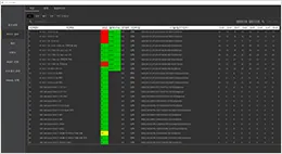
4. Gateway - Converts IEC 61850 to DNP - Communicates with master stations via DNP - Communicates with IEDs/RTUs via IEC 61850 and DNP - Main/backup redundancy
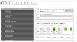
5. Engineering Tool - Configures monitoring/control/measuring points - Sets point attributes - Saves configuration history to the DB
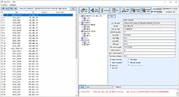
6. IEC 61850 Client - Manages IED connections - Collects/controls IED data - IEC 61850 protocol
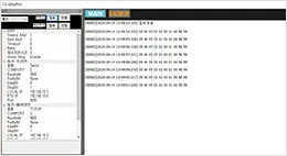
7. DNP Protocol - Manages RTU connections - Collects/controls RTU data - DNP protocol
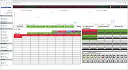
8. Monitoring/diagnosis device - Monitors and diagnoses IEC 61850 - Wireshark-based IEC 61850 analysis - Saves and extracts PCAP files