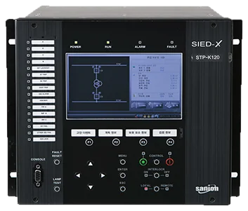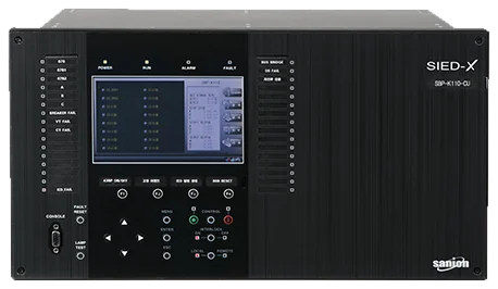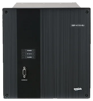
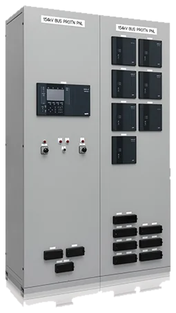
Bus Protection Panel
Sanion’s 154kV busbar protection panel, which is developed and manufactured by pure domestic technology, consists of multiple bay units (BU) which monitor the current of each feeders connected to the busbar and collect status information of circuit breakers and disconnecting switches. It also consists of a central unit (CU) which performs current differential protection by using the current values and status information received from the bus. In addition, CU measures the voltage of each busbar to use it for fault detection.
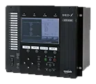
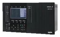
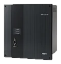
Definition
- A busbar is one of the power system facilities in the substation, which concentrates and re-distributes electric power by connecting transmission lines and transformer banks. A busbar fault produces a very large fault current, and if clearing is delayed it may spread into a much wider fault. Busbar structures include radial, ring and double busbars; the double busbar is most widely used because it shortens fault duration and offers high reliability and good maintainability. In particular, the 345kV class adopts a 1.5CB structure with three circuit breakers between the two busbars. The 154kV busbar protection panel provides current differential protection for fast and accurate fault detection in a double busbar structure, isolating faults and safely protecting the busbar. Busbar protection is internally divided into separate zone protection (zone 1 or 2) to identify the faulted busbar and overall busbar protection that detects a fault anywhere on the busbar. For example, if both the overall protection and the zone 1 protection detect a fault, the function determines that the fault is on busbar No. 1.
Main functions
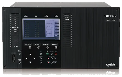
- Phase-segregated current differential protection (87B)
- Undervoltage based fault detection (UV/UVS/UVD)
- Overcurrent protection (50BF) for circuit breaker failures
- CT and PT failure detection and alarming
- External fault detection to prevent wrong tripping due to CT saturation
- Busbar-bridged protection according to the status conditions of DS's and alarming for abnormal conditions
- Automated compensation for different CT ratios
- Communication with multiple BUs based on high speed serial communication (1Gbps, fiber optic)
- Fully IEC 61850 compliant, Edition 1
- Self-monitoring on a regular basis
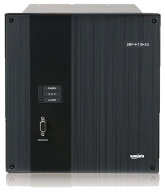
- Current measurement and status monitoring of CB, DS and BFI for two feeders
- Communication with CU based on high speed serial communication (1Gbps, fiber optic)
- Self-monitoring on a regular basis
Specification
| Division | Item | SBP-K110-CU | SBP-K110-BU |
|---|---|---|---|
| Ratings | Input power | DC 90~140[V],60Hz | DC 90~140[V],60Hz |
| Rated voltage(PT) | 110/√3[V] | - | |
| Rated current(CT) | - | 5[A] | |
| Digital output | 10[A] : 250VAC 24 points | 10[A] : 250VAC 14 points | |
| Digital input | DC 70 ~ 150[V] 24 points | DC 70 ~ 150[V] 24 points | |
| Communication | Communication port | RS-232, Ethernet, Fiber Optic | RS-232, Fiber Optic |
| Protocol | IEC61850, TCP/IP | - | |
| Time | IRIG-B, SNTP |